Phase-Locked Loops (PLLs): Theory, Operation, and Applications
A Phase-Locked Loop (PLL) is a critical component in many electronic systems, used for synchronizing signals, frequency synthesis, and signal recovery. This blog provides a detailed explanation of the PLL, its operation, and the underlying theory, including relevant equations and diagrams.
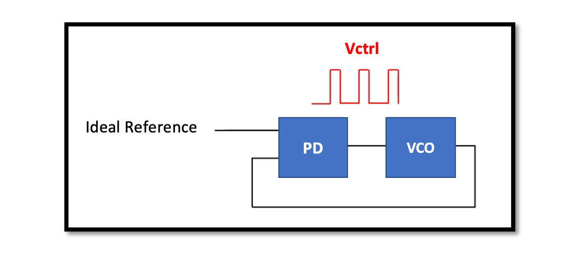
PLL is a control system that generates an output signal whose phase is related to the phase of an input signal. In its simplest form, a PLL consists of a Voltage-Controlled Oscillator (VCO) and a phase detector (PD). The PD compares the phase of the input signal 𝑤𝑖𝑛 with the phase of the VCO output and converts the phase difference into a voltage. This voltage, VF, adjusts the frequency and phase of the VCO to match the input signal. The goal of the PLL is to minimize the phase difference, effectively locking the VCO’s phase and frequency to that of the input signal.
How PLLs Work
A PLL operates by continuously adjusting the VCO based on the error signal from the phase detector. The PD converts the phase difference between 𝜙𝑖𝑛 (input phase) and 𝜙𝑜𝑢𝑡 (output phase) into a control voltage (VF). This control voltage then adjusts the VCO to bring 𝜙𝑜𝑢𝑡in line with 𝜙𝑖𝑛.
Equations Governing PLL Operation
The control voltage VF often contains ripple, which can modulate the VCO and produce sidebands. The equation VF = V0cos[wint + KVCO∫Vm sin (w1t)dt] represents the output of the VCO when influenced by the control voltage with ripple. Expanding this equation, we get:
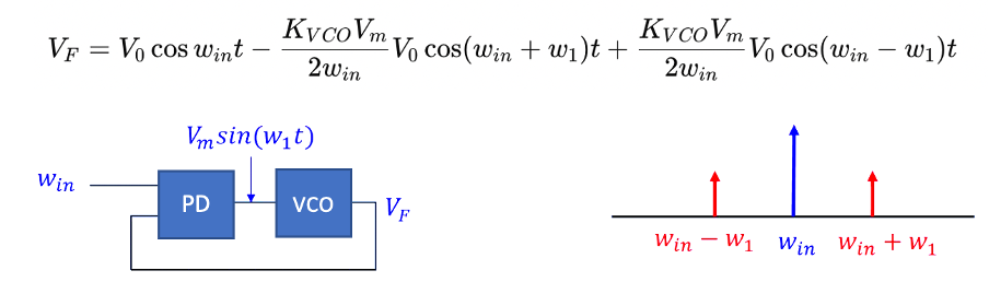
This shows that the output of the VCO contains not only the desired frequency 𝑤𝑖𝑛win but also additional components at frequencies 𝑤𝑖𝑛+𝑤1win+w1 and 𝑤𝑖𝑛−𝑤1win−w1. These sidebands are a result of the modulation of the VCO by the ripple in the control voltage Vmsin(w1t).
The frequency spectrum diagram illustrates this by showing peaks at 𝑤𝑖𝑛 (the main frequency), win−w1, and win+w1 (the sidebands). The sidebands’ presence indicates the influence of the control voltage ripple on the VCO output, demonstrating how the PLL system modulates the VCO and produces these additional frequency components. In addition to synchronizing signals, a phase locked loop can track an input frequency, or it can generate a frequency that is a multiple of the input frequency.
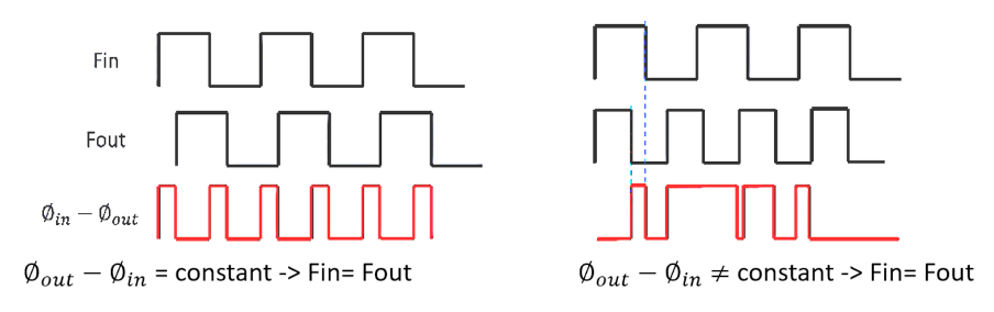
Diagram Explanation: The diagram below illustrates the basic operation of a PLL and how it ensures that the input frequency 𝐹𝑖𝑛 matches the output frequency 𝐹𝑜𝑢𝑡.
- Basic PLL Structure:
- Input (𝐹𝑖𝑛): The reference frequency signal entering the PLL.
- Phase Detector (PD): Compares the phase of the input signal (𝐹𝑖𝑛) with the phase of the VCO output (𝐹𝑜𝑢𝑡).
- Output (𝐹𝑜𝑢𝑡): The frequency signal produced by the VCO, which the PLL aims to synchronize with 𝐹𝑖𝑛.
- The phase of the input and output signals are denoted as 𝜙𝑖𝑛 and 𝜙𝑜𝑢𝑡, respectively.
- Phase Difference and Frequency Equality:
- To ensure 𝐹𝑖𝑛=𝐹𝑜𝑢𝑡, the phase difference 𝜙𝑜𝑢𝑡−𝜙𝑖𝑛 must remain constant. If this phase difference is constant, it implies that the frequencies are equal because there is no drift over time.
- Waveform Analysis:
- The waveforms in the diagram illustrate two scenarios:
- When the phase difference is constant (𝜙𝑜𝑢𝑡−𝜙𝑖𝑛=constant).
- When the phase difference is not constant (𝜙𝑜𝑢𝑡−𝜙𝑖𝑛≠constant).
- Left Part of the Diagram: Here, 𝐹𝑖𝑛Fin and 𝐹𝑜𝑢𝑡have synchronized phases, resulting in a constant phase difference. This is depicted by the consistent time intervals (𝜏1τ1) between corresponding rising edges of the input and output signals. The red waveform at the bottom shows a constant phase difference, confirming that 𝐹𝑖𝑛=𝐹𝑜𝑢𝑡.
- Right Part of the Diagram: In this scenario, 𝐹𝑖𝑛 and 𝐹𝑜𝑢𝑡 are not synchronized, leading to a varying phase difference. This is indicated by differing time intervals (𝜏1 and 𝜏2) between the rising edges of the input and output signals. The red waveform at the bottom shows a non-constant phase difference, indicating that 𝐹𝑖𝑛≠𝐹𝑜𝑢𝑡.
- The waveforms in the diagram illustrate two scenarios:
Take our entry level course (Below) for free using coupon code RAHRF101BLOG
RF Fundamentals, Basic Concepts and Components – RAHRF101
For limited time take an additional 10% off of all our courses using coupon code RFCERT10
Rahsoft RF Certificate and courses
Practical Implications of PLLs
In real-world applications, PLLs are used in various electronic devices and systems, including:
- Frequency Synthesis: Generating a range of frequencies from a single reference frequency.
- Demodulation: Extracting the original information-bearing signal from a modulated carrier wave.
- Clock Recovery: Synchronizing the clock signal in digital communication systems.
Understanding the principles and operation of PLLs is essential for designing and troubleshooting these systems. By maintaining a constant phase difference and effectively managing control voltage ripple, PLLs ensure accurate frequency synchronization and stable performance.
Conclusion
Phase-Locked Loops are fundamental components in modern electronics, providing critical functionality for frequency and phase synchronization. Through the principles and equations discussed, we can appreciate the complexity and importance of PLLs in various applications. The diagrams and waveforms help visualize the operation and underscore the necessity of maintaining a constant phase difference for effective frequency locking.

Learn more about this topic by taking the complete course ‘Phase Lock Loop System Design Theory and Principles RAHRF469’. Watch the course videos for more detailed understanding. Also checkout other courses on RF system and IC design on https://rahsoft.com/courses/. Rahsoft also provides a certificate on Radio Frequency. All the courses offer step by step approach.
You may also like
Understanding Quadrature Amplitude Modulation (QAM) and Its Applications