Analyzing VCO Phase Noise and Transfer Functions in PLLs
A Phase-Locked Loop (PLL) is a feedback control system that synchronizes the phase of its output signal with a reference signal. This synchronization is crucial for many applications such as frequency synthesis, clock generation, and demodulation in telecommunications, computers, and various electronic systems. PLLs are extensively used to ensure signals are in phase, which is vital for the stability and accuracy of these systems.
Importance of VCO Phase Noise
The Voltage-Controlled Oscillator (VCO) is a key component of PLLs. It generates an oscillating signal whose frequency is controlled by an input voltage. The phase noise of a VCO, which refers to the rapid, short-term random fluctuations in the phase of the signal, can significantly affect the performance of a PLL. High phase noise can cause timing jitter and reduce spectral purity, leading to degraded performance in communication systems.
Deriving the Transfer Function for VCO Phase Noise

To understand how VCO phase noise affects the output of a PLL, we need to derive the transfer function that relates the output phase noise to the VCO phase noise. This transfer function is derived using the block diagram of the PLL:
The block diagram includes:
- Phase Frequency Detector (PFD): Compares the phase of the reference signal and the feedback signal from the VCO.
- Charge Pump (CP): Converts the output of the PFD to a current that charges or discharges the loop filter.
- Loop Filter (LPF): Filters the charge pump current to generate a control voltage for the VCO. For simplicity, we assume an R1 and C1 simple RC filter.
- Voltage-Controlled Oscillator (VCO): Generates an output frequency proportional to the control voltage.
- Divider (1/M): Scales down the VCO frequency for comparison with the reference signal.
The output phase noise (Φout) is related to the VCO phase noise (Φvco) through the transfer function:

Where:
- S is the complex frequency variable in Laplace transform.
- ζ is the damping factor.
- ωn is the natural frequency of the PLL.
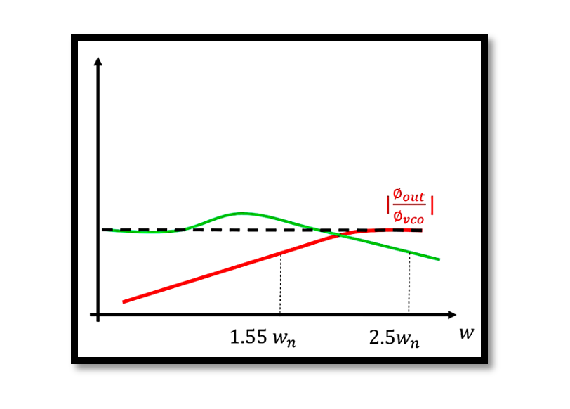
This equation shows that the transfer function behaves as a high-pass filter to the VCO phase noise. At high frequencies, the phase noise passes through to the output with little attenuation. At low frequencies, the PLL suppresses the phase noise.
Detailed Analysis of the Transfer Function
To derive the above transfer function, consider the following steps:
Model the Phase Detector and Charge Pump: The Phase Frequency Detector (PFD) and Charge Pump (CP) create an error signal proportional to the phase difference between the reference signal and the VCO output. This error signal is converted to a control voltage by the loop filter.
Loop Filter Design: Assume a simple RC filter for the loop filter. The transfer function of a simple RC filter is

VCO Dynamics: The VCO output frequency is directly controlled by the loop filter voltage. The VCO transfer function is typically Kvco/s, where Kvco is the VCO gain.
Closed-Loop Transfer Function: The closed-loop transfer function of the PLL is derived by combining the transfer functions of the PFD, CP, LPF, and VCO. The characteristic equation of the PLL is:

By simplifying this equation, we obtain the transfer function for the VCO phase noise:

Phase Noise Spectrum Analysis
The phase noise spectrum is crucial for understanding the impact of phase noise in PLL systems. The output phase noise spectrum (SΦout) is derived by multiplying the VCO phase noise spectrum (SΦvco) by the magnitude square of the transfer function:

This equation shows how the phase noise from the VCO is shaped by the PLL’s transfer function.

Case Study: Low Bandwidth
Consider a PLL with low bandwidth where 1.55ωn≪ωc. The phase noise at the output in this scenario is influenced by the low-pass characteristics of the loop filter. The phase noise spectrum is:


This equation helps in analyzing how the phase noise at different frequency offsets is affected by the PLL bandwidth.
Take our entry level course (Below) for free using coupon code RAHRF101BLOG
RF Fundamentals, Basic Concepts and Components – RAHRF101
For limited time take an additional 10% off of all our courses using coupon code RFCERT10
Rahsoft RF Certificate and courses
Suppressing VCO Phase Noise
Suppressing VCO phase noise involves adjusting the PLL parameters to filter out more noise. One effective strategy is to increase the 3dB bandwidth of the loop filter. By moving the 3dB bandwidth to higher frequencies, the PLL can attenuate more of the VCO phase noise. However, there is a trade-off between spur suppression and phase noise reduction. Increasing the bandwidth may allow more spurious signals to pass through the loop filter.

Conclusion
Understanding and managing VCO phase noise is essential for designing high-performance PLLs. The derived transfer function and phase noise analysis provide insights into optimizing PLL design. By carefully selecting PLL parameters and adjusting the loop filter bandwidth, it is possible to achieve the desired balance between noise suppression and system stability. This detailed understanding helps engineers design more robust and efficient PLL systems for various applications.

Learn more about this topic by taking the complete course ‘Phase Lock Loop System Design Theory and Principles RAHRF469’. Watch the course videos for more detailed understanding. Also checkout other courses on RF system and IC design on https://rahsoft.com/courses/. Rahsoft also provides a certificate on Radio Frequency. All the courses offer step by step approach.
Tag:Phase Noise, PLL, VCO, VCO Phase Noise


