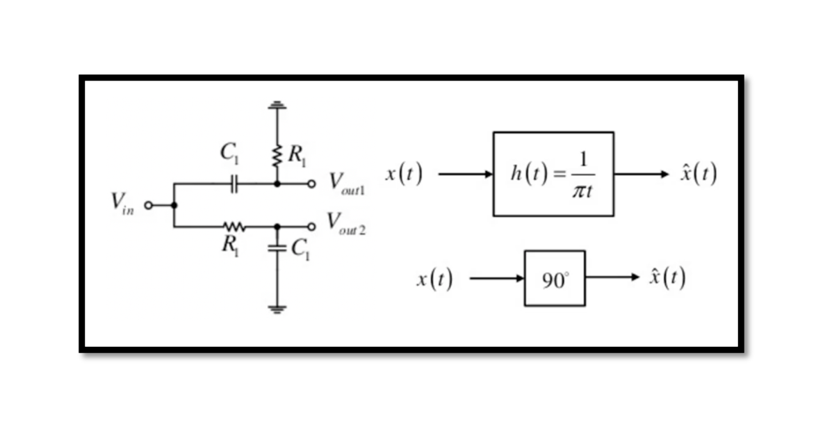
How is the 90˚ phase shift implemented? There are two methods that we will discuss here to implement a 90-degree phase shift inside a receiver. The first method is the RC-CR network and the second method is Quadrature downconversion. In …
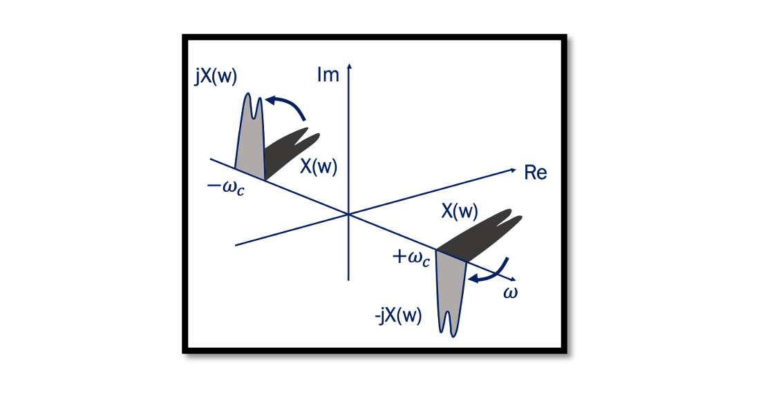
90 degree Phase Shift – Quadrature Down Conversion When a signal becomes its own image it corrupts the desired channel and the solution to this problem is Quadrature Down Conversion. Read more about the Image problem. The below plot shows …
Have you ever tried exploiting constellation diagrams to locate the source of bugs in your wireless link? Yes! digital communication systems can be diagnosed for several impairments by visual inspection of constellations diagrams. One may ask why we want to …
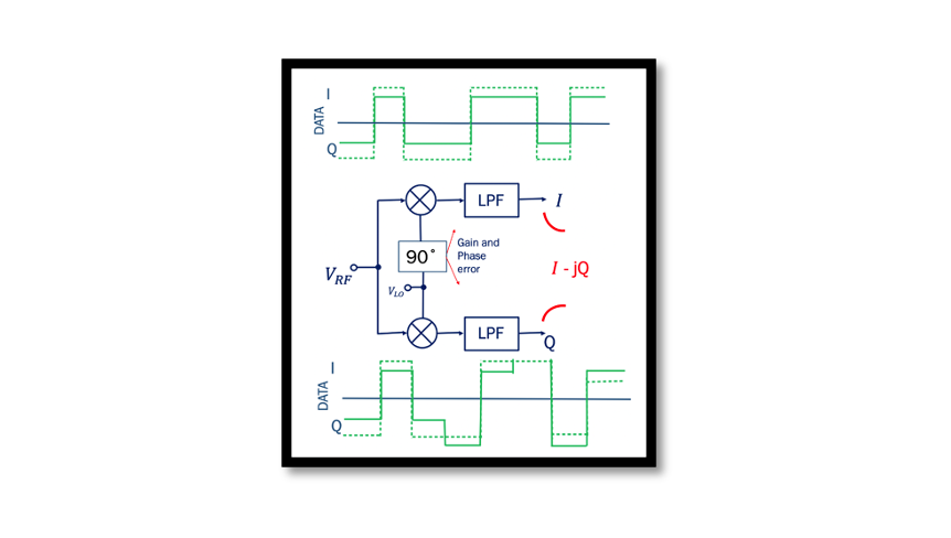
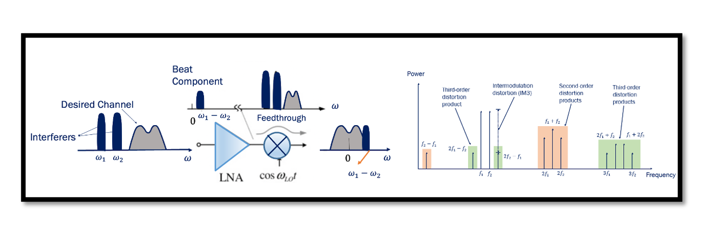
What is the drawback of quadrature down conversion? In this blog, we will be looking into the IQ mismatch and how it affects our signal. Refreshing the memory from a previous blog on Quadrature down conversion. Looking at the below …
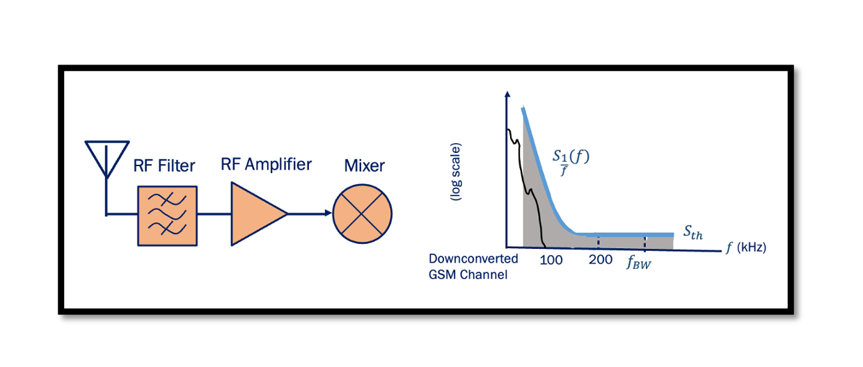
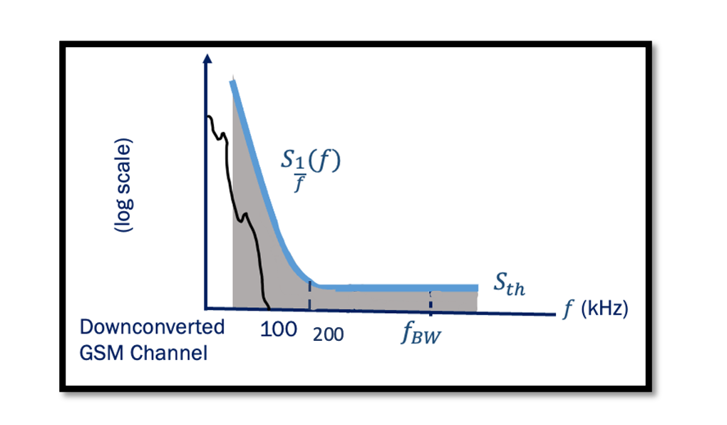
How do RF Front-End components effect the Flicker Noise Penalty? We will first discuss the effect of the Antenna, LNA, and Mixer on the Flicker Noise Penalty then use an example to show if it’s good or bad for the …
Are you wondering about calculating Phase-Noise requirements for a certain wireless communication link? If yes, the article is for you! This series of blogs addresses the following common questions that engineers usually come across while designing RF systems: What is …
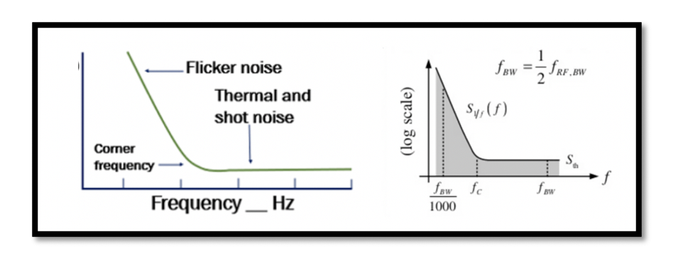
Which noise is dominant in the baseband? It is flicker noise, which is dominant in the baseband, if the signal gets translated to the intermediate frequency, we will not have a flicker noise problem. The flicker noise is only dominant …
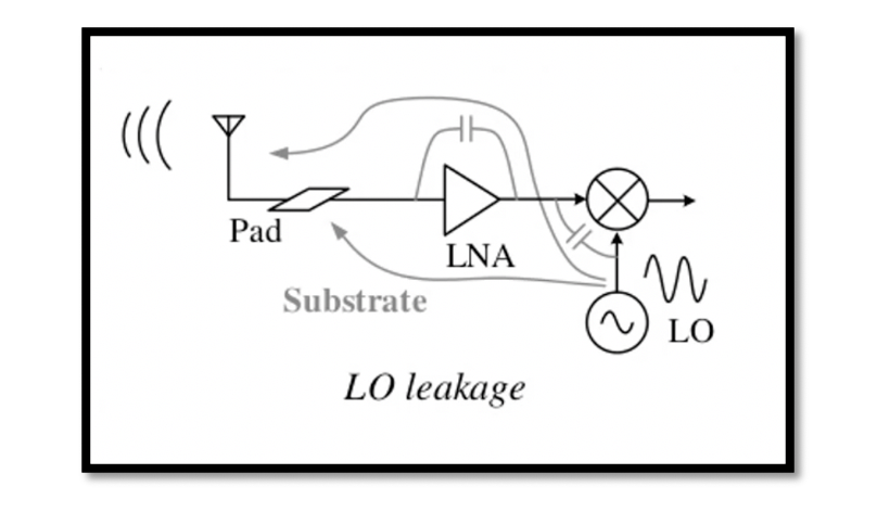
What are the drawbacks of Direct Conversion Receivers? DC offset is coming from local oscillator leakage. The local oscillator leakage problem causes a large DC offset in the baseband and saturates the baseband circuits. Read more. LO Leakage – Direct …
What is Flicker Noise? Previously we discussed different categories of noise (pink, white, and band-limited noise). Different types of noise can be specific to devices. Read about types of noise in RF devices. Flicker Noise is one of the types …
Local Oscillator leakage Direct conversion receiver emits fraction of its LO power from its antenna. Isolation is a measure of the leakage, or feedthrough, from one port to another. The figure below shows the leakage from different ports of mixer. …

