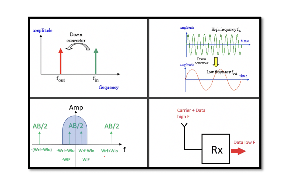
Down Conversion in RF Receiver
Down Conversion
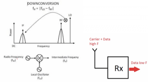
Down conversion occurs in the receiver. Before transmitting the data, it is shifted to high frequency and is captured by the antenna and passed on to the receiver. The captured signal is then shifted from high frequency to intermediate or low frequency in the receiver. Down conversion is similar to demodulation, where the modulated data signal is translated to low or intermediate frequency. This down conversion is done by the mixer. As shown in the below figure, the radio frequency is captured by antenna, amplified by low noise amplifier (LNA) and mixed with local oscillator (LO) to shift the data to low or intermediate frequency.
Take our entry level course (Below) for free using coupon code RAHRF101BLOG
RF Fundamentals, Basic Concepts and Components – RAHRF101
For limited time take an additional 10% off of all our courses using coupon code RFCERT10
Rahsoft RF Certificate and courses
Mixer for down conversion
RF Mixer is a three-port passive or active device that modulates or demodulated a signal. The main purpose of mixer is to shift the fre1quency of an electromagnetic signal without changing or having an effect on other characteristics like phase and amplitude of the initial signal. Up conversion happens inside a transmitter and down conversion inside the receiver.
Carrier signal is a cosine signal with high frequency that carries the information. Data is modulated which has IF frequency (in up conversion) is mixed with LO having carrier signal (cos 2πfot) to give the output signal, as shown below.
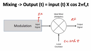
Down conversion by mixing
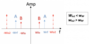
Let’s assume that the modulated data is a cosine wave. Input = Acos (wRFt). In frequency domain the spectrum can be shown, where Wrf & -Wrf are the data and Wlo & -Wlo is carrier wave with angular frequency of Wlo1. The local oscillator produces carrier wave Carrier = Bcos(wlo1t). So mixing these two signals we will have the output.
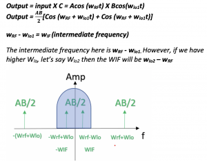
At the output of mixer we can see the signals are shifted and we get four type of components. Now filtering will remove other components as they are in higher frequencies.
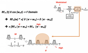
This is a very basic structure of a receiver explained in the diagram. We have RF channel, win is RF, LO, mixer & low pass filter. In mixer we are multiplying our signal with the cosine wave and as we know that in frequency domain it will become a convolve and the fourier transform of cosine wave is delta, so after this the result of this convolution will be four signals and designing a low pass filter we can get rid of the high frequency components to get intermediate frequency.
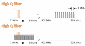
So in summary the down conversion occurs inside the receiver. If there is modulated channel with radio frequency (RF), then inside the receiver the RF is shifted to IF by mixing radio frequency channel with a local oscillator using the mixer block. Now we have the channel in intermediate frequency and then extra amplification, filtering and demodulation is done. Band are allocated to different applications like GSM, Wifi, TV. The channels represent users, so every band consists of numbers of narrowband channels. First the band is selected and then the channel is selected for our band. This band selection is happening in RF frequency so we can only make low Q filter and not the High Q filter as there is lower selectivity, the filter is not really sharp. When the band is shifted later on to intermediate frequency the high Q filter can be designed which has a high Q to pick desired channel. So if you have a band as shown in the above diagram with different channel then shift it to IF and using high Q filter desired channel is selected.


