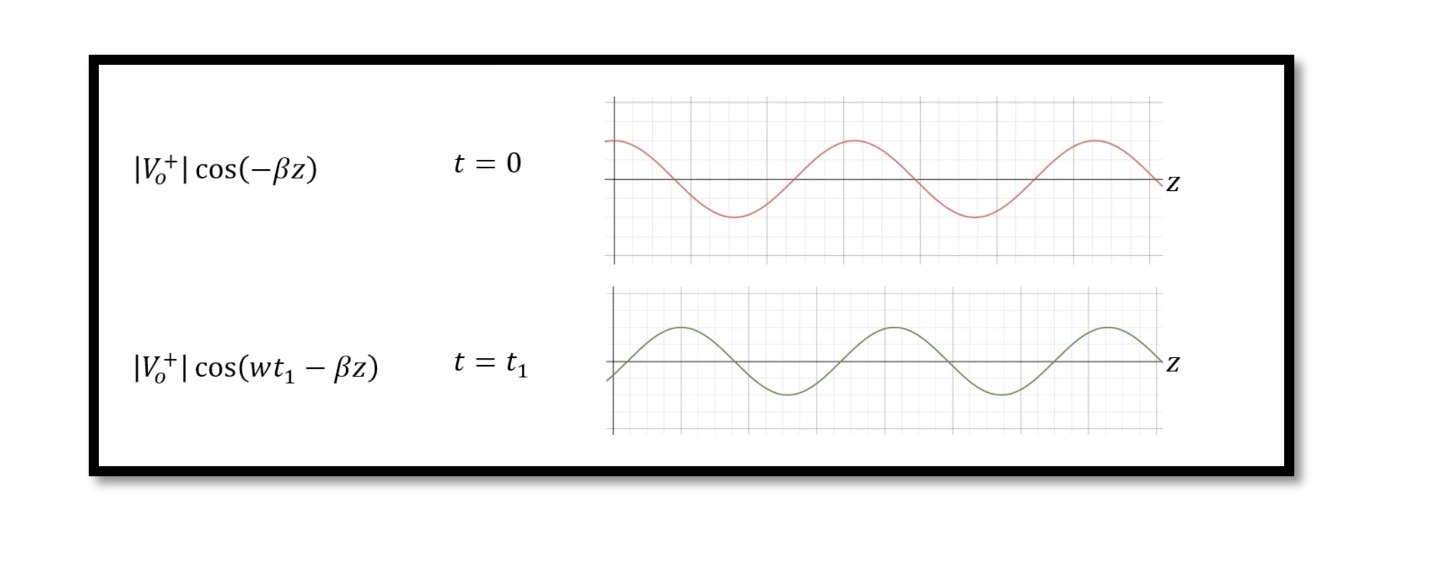
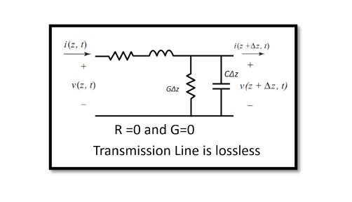
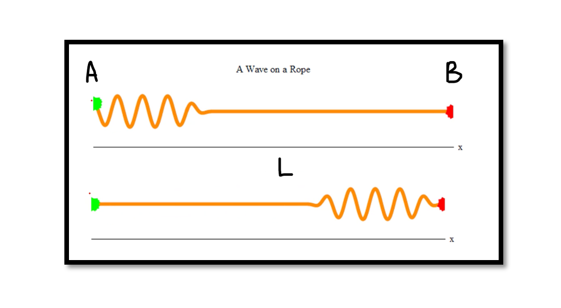
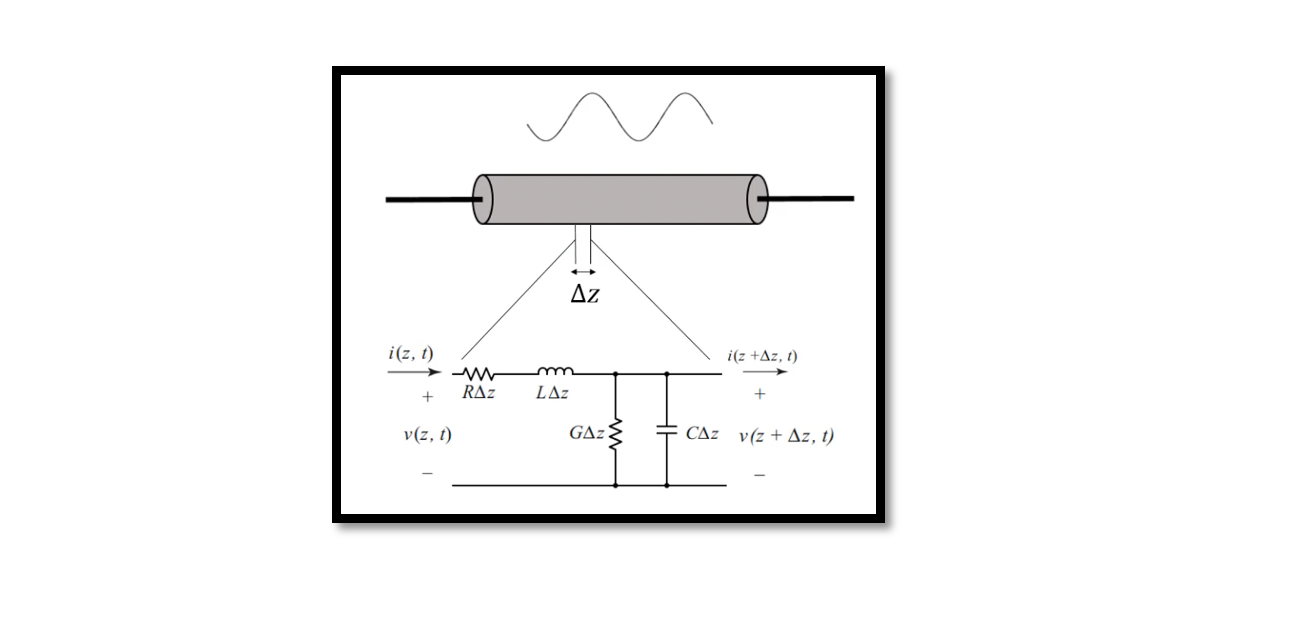
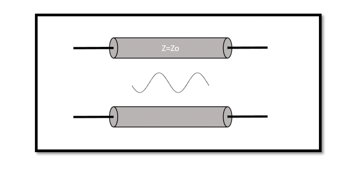
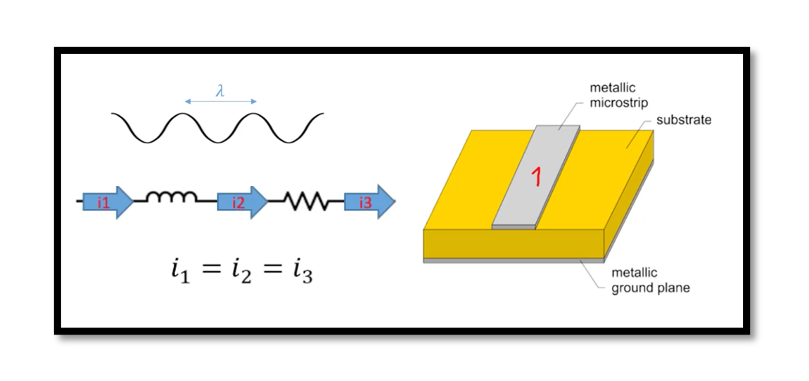
In previous blogs, we discussed about wave propagation where we said that the voltage on the transmission line will propagate and have wave like behaviour. In this section, we will prove this theory. We can understand the behaviour of voltage …
In a transmission line, the four primary distributed parameters are resistance (R), capacitance (C), inductance (I), and conductance (G). The secondary constants are the characteristic impedance (Zo) and complex propagation constant (y) that are derived using the primary parameters. Transmission …
What is characteristic impedance in Transmission lines? In this blog, we are going to talk about the characteristic impedance of a transmission line. Let’s derive the formula for characteristic impedance by finding the relationship between current and voltage from the …
In the previous blog what is transmission line, we discussed that we are dividing a transmission line into many incremental segments and assuming each segment is lumped network because of its short length. In this blog, we will talk about …
RF Transmission Line In simple words, the purpose of an RF Transmission line is to transmit RF power from one point to another efficiently. Hence, considering the best RF cable hold an important role in radio systems. The categories include …
In this blog, we will talk about distributed versus lumped analysis for a basic understanding of the transmission line concept, why we use transmission line, what is the lump component and why it’s a distributed element. In later parts, we …
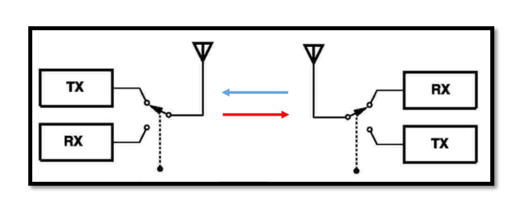
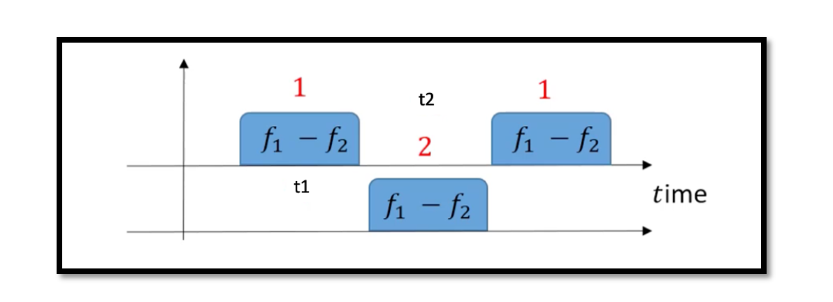
TDD Merits Transmitters are turned off during reception, so the two paths don’t interfere. TDD allows direct peer-to-peer communication between two transceivers hence no need for the system between them. Only one band is allocated so we don’t need to …
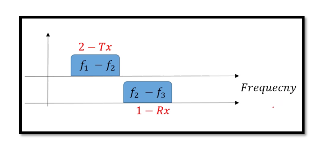
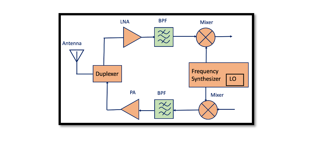
Frequency Division Duplexing In Frequency Division Duplexing is a full-duplex model of transceiver where different bands of frequencies are utilized for Tx and Rx and the data is transmitted and received at the same time. Bandpass filters are used to …
Time Division Duplexing (TDD) In the previous blog, we discussed about the basic structure of the transceiver and the duplexer block. Duplexer acts as a decision block like a switch between the transmitter and receiver part. There are different types …
What is a Transceiver? A transceiver is a combination of transmitter and receiver, hence the name transceiver. The transmitter and receiver share the circuitry. It can both transmit and receive radio waves to communicate with another device. Transceivers are widely …

