Complex Power in AC Circuits
The combination of real and imaginary values makes up a complex number. It is represented in the form of “R+jX,” where R is the real part and jX is the imaginary part. In a two-dimensional cartesian plane, the real components are plotted on the horizontal axis, and the imaginary parts are plotted on the vertical axis.
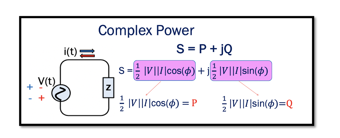
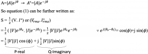
By definition, power is the product of voltage and current. The current and voltage can be represented in their phasor forms, with amplitude and phase. Read about phasors and RMS. Therefore, the complex power is the product of the RMS value of the phasor voltage and conjugate of the phasor current. In a circuit with impedance Z, the voltage across the impedance will be v(t) and current i(t) with RMS values Vrms & Irms and phase θv & θI.

I* the conjugate of the phasor of the current corresponding to its RMS value. For example, to show the conjugate of A, it is represented in the phasor form with the same magnitude but negative phase:

The complex number S is now represented in the complex form with the real part P and the imaginary part Q.

The ‘P’ in the equation shows the average power. By definition, when average power is represented in the phasor form is equal to P or the real part of the complex power. This power is also called active power. Read more about average power. Average power or active power forms the real part of the complex power. The imaginary part Q of the complex power is the reactive power.

Active power and Reactive power
The active power (P) is the true or real power consumed or utilized in an AC circuit and is measured in watts. In a circuit, when the power flows from the source to the load, it is called positive power. In a purely resistive circuit, power remains positive at every instant of time; that is, the power flows from source to load. This power is called active power.
Take our entry level course (Below) for free using coupon code RAHRF101BLOG
RF Fundamentals, Basic Concepts and Components – RAHRF101
For limited time take an additional 10% off of all our courses using coupon code RFCERT10
Rahsoft RF Certificate and courses
The power that continuously oscillates back and forth between the load and source without doing any essential work is called the reactive power, caused by non-linear devices like capacitors and inductors in an AC circuit and measured is VAR, which is Volt Ampere Reactive. The reactive power is not considered useful. The reactive power depends on the load impedance’s reactance in the circuit and measures energy exchange between the source and the load’s reactive part.
A purely resistive circuit implies that the reactive power equals 0. The load is inductive when the reactive power is greater than 0 (Q>0), which means the power is lagging. When reactive power (Q) is less than 0 (Q<0), the load will have capacitive nature.
In an inductive circuit, the current lags voltage, and in a capacitive circuit, the current leads the voltage. Power measured at any instant in the capacitive circuit can be either positive or negative. Negative power indicates the flow of power from the load to the source. This happens when the capacitor stores the energy in the positive cycle and releases it in the negative half cycle; hence, we get a negative power. It is not actual power and is not consumed.
Relation between complex power and impedance


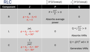
Working in the RF systems and blocks, it is crucial to know Resistor R, Inductor L, and Capacitor C’s behaviour in terms of power. As we know from the previous sections, the resistor’s impedance is constant and is independent of frequency. In a resistive circuit R, there is only average power, and the phase is 0 hence, ? is 0 so there is no reactive power. ? = θv-θI = 0, θI=0. We can say that the resistor absorbs the average power.
The reactive power is stored and discharged by the inductors and capacitors. In an inductive circuit, the frequency is directly proportional to the impedance; when frequency increases, the impedance increases. When ? is 90, the average power becomes 0. ? = θv- θI =>90°, θc = 90°. Therefore, the inductance never absorbs the average power. In order to absorb the power, the circuit should have a resistor. It only has the reactive positive part, which absorbs the reactive power. In a capacitive circuit, the real part has the value 0, as ? = θv- θI = -90°, θc = -90°. The imaginary part has a negative value due to negative power flow, and it generates the reactive power measured in VAR (Volt Ampere Reactive).

 Learn more about this topic by taking the complete course ‘

